Building a DIY Studer CR Monitor Output 1.960.151
Tools
For this project, you just need a soldering iron, a stanley knife, some wire strippers and a continuity tester (multimeter would work fine).
Purchases
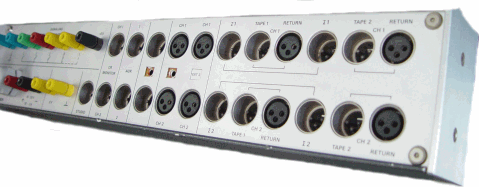
Here is a list of purchases and rough costs. I used 1/4" female jacks for my chassis connectors as my patchbay is 1/4" balanced, but you could just as easily replace these with XLR chassis connectors if required. Total cost was £84.26. You could also save on the DB50 and cabling by soldering that up yourself, but I decided that life was too short as cables were available with the DB50 already soldered on.
Assembly
Once you've bought all the bits, cut the male DB50 plug off, then strip back 51cm of outer sheathing of the cable using the stanley knife. This should leave you with a female DB50 and 50 assorted wires plus a shield wire.
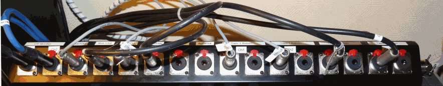
The next job is to thread the wire into the wall box via the metal gland. You may need an extra washer for this as hole in the wall box is about 20mm itself
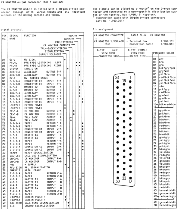
Once threaded comes the tedious part, you now have to strip the end off all of the 50 cables and label them up by using your continuity tester and the female DB50, which has 1-50 labeled already on it.
Once labeled, you just need to decide which of the inputs/outputs you require from the list below and solder them up. I soldered all of the shield connections to the shield wire and 2 other wires for each balanced connection.
I also took the stanley knife to the DB50 connector as it was a bit snug in terms of fit initially. A little bit of trimming of the plastic surround later and it fit much better.